Brand:HIMA
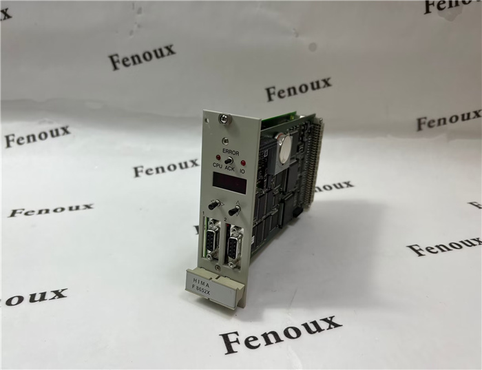
Model number:F8652X
Colour:new
Warranty: 12 months
Lead Time:3-day working day
Country of origin: USA Price: Please contact us
Product weight:0.4kg
Shipping Port: Xiamen, China
Payment: Bank of Chicago, Bank of Singapore
Express cooperation: fedex, DHL, UPS and your express account
Service: Professional Sales provides 24 hours /7 days online service
Description:
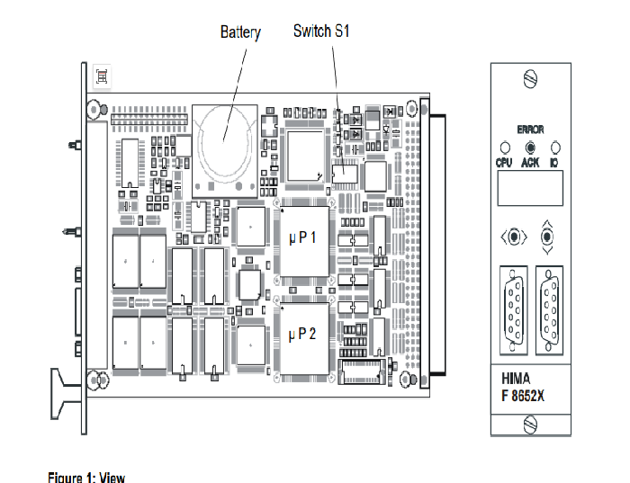
Diagnostic display of the central module
– Four digit alphanumerical display,
– two LEDs for the general display of errors (CPU for the central modules, IO for the testable
input/output modules),
– two toggle switches to request detailed error information,
– push-button ACK resets the error indication;
in failure stop ACK behaves like restarting the system.
For further information on the diagnostic display and lists of error codes, refer to the documentation
"Functions of the operational system BS 41q/51q" (also on ELOP II CD).
Notes for start-up and maintenance
– Lifetime of the buffer battery (without voltage feeding):
1000 days at TA = 25 °C
200 days at TA = 60 °C
– It is recommended to change the buffer battery (CPU in operation) at the latest after 6
years, or with display BATI within three months
(Lithium battery, e.g. type CR 2477N, HIMA part no. 44 0000018)
– Check the bus station no. and transmission rate at switch S1 for correct settings
– The F 8652X can be used to replace the previous moduls: F 8652, F 8652A and F 8652E!
Special features of the central module:
– Self-education: from operating system BS41q/51q V7.0-8 (05.31)
– ELOP II TCP: from operating system BS41q/51q V7.0-8 (05.31)
Further informations about the bus station no., ELOP II TCP, loading of operating systems and
application programs (self-education) et al. corresponding to the central module you will find in
the data sheet of the F8627X as well as the operating system manual of H41q/H51q and the
safety manual of H41q/H51q.
Pin RS 485 Signal Meaning
1 - - not used
2 - RP 5 V, decoupled by diodes
3 A/A’ RxD/TxD-A Receive/Transmit Data A
4 - CNTR-A Control signal A
5 C/C’ DGND Data Ground
6 - VP 5 V, positive pole of power supply
7 - - not used
8 B/B’ RxD/TxD-B Receive/Transmit Data B
9 - CNTR-B Control signal B
Before removing a central module its fixing screws must be completely
loosened and freely movable. Remove the module from the bus board
by pushing the ejection lever (front label) top down and quickly removing
in an upward motion to ensure that faulty signals are not triggered
within the system!
To attach the module, place it on the terminal block and press it
inwards as far as it will go. This action should be performed quickly to
ensure that faulty signals are not triggered within the system!
Shipping Port: Xiamen, China
Payment: Bank of Chicago, Bank of Singapore
Express cooperation: fedex, DHL, UPS and your express account
Service: Professional Sales provides 24 hours /7 days online service
Relevant details:
F4101 (17.003)
F4102
F4110 (17.058)
F4111a (17.021)
F4304 (17.026)
F7126
F7131
F7553 (17.037)
F8601 (17.036)
F8620/4
F8650 (17.053)
F8650E


