Gray (pair) for IOL1
l Violet (pair) for IOL2
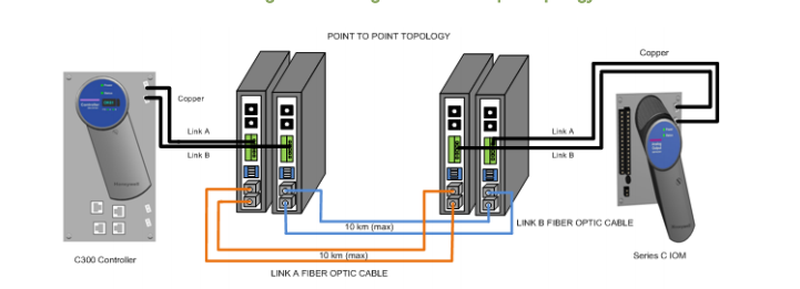
Refer to the Key features of single mode FOE section for more information on the compatible fiber
optic cables.
13.6.3 Fiber Optic Extender interface cable
Specific cable types must be used for the fiber optic interface.
ATTENTION
The proper interface cable must be used for the Series C topology. Use of the incorrect cable
results in faulty and/or corrupted IOL communications.
The fiber link is a passive subsystem and is essentially transparent to the system operation. It does
not increase or decrease traffic or impact other capabilities of the I/O system. In addition, the
following designations occur for these cables:
Cable Cable color A-link tab color B-link tab color
IOL1 Gray Yellow Green
IOL2 Violet Yellow Green
13.6.4 Fiber optic cable - length factors
The maximum run of the fiber optic cables is limited by the optical power budget of 15dB. Standard
cables support 10 km.
13.6.5 Standard I/O link extender maximum cable span calculation
The following calculation MUST be used to ensure that the number of planned splices and the
cable choice supports the necessary cable span distance.
The maximum cable span calculation (in km) is as follows:
Max Span = (Available Optical Power - Losses in Splices)/(Max Loss per Cable
Type)
13.6.6 Available standard I/O link extender optical power
The available optical power calculation is as follows:
Transmit Power - Minimum Receiver Sensitivity - Power Loss Over Time =


