For this type of connection, you need four wires. Two wires provide power to the sensor and the
other two wires connect the pulse output from the sensor to the PIM. This example shows the field
sensor connected to channel 1 but the procedure applies to the remaining channels.
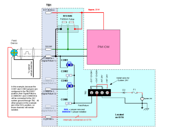
The internal +24 Vdc supply, TB1, and TB2 are used to supply sensor power. This is accomplished
by connecting the corresponding channel’s FLDPWR1+ pin and COMMON1 pin to the positive and
negative power leads of the field sensor respectively. To complete the circuit, place the jumper wire
across the pins of the COM1 terminal block as illustrated in the above diagram so that so field
return is tied to COMMON1.
Install wires at TB2 as illustrated in the above diagram to feed all eight of the FLDPWR(x) to TB1.
There is no need to add individual wires from FLDPWR(x) to the +EXT 12V/24V connector at TB2 as
this is provided by internal copper tracks on the IOTA.
For clarity, the LED DS1 and other components are not shown in the above diagram. See also
figure PIM TB1 pin assignments.
Example 2: Sensor powered from Series C System +24 V internal supply.
Power connections directly made through TB2
The following figure displays a sample diagram where the sensor is powered from Series C system
+24 V internal supply and the power connects are directly made through TB2.
- 228 -
Chapter 6 - Series C PIM connectivity
Figure 6.10 System +24 V internal supply used. Power connections made through TB2
In this example, the power connections are made through TB2 only.
All COM(x) jumpers in this example are removed (ISOL). If a jumper is installed (BUSSED), the
respective signal common will be connected to the 24V system ground through TB2.


