Power supplies and battery backup
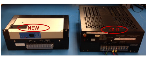
1. Make a note of the power supply locations.
2. Check the current loading (amperes) on each supply.
3. Measure the DC output voltage and record the value here.
4. Check whether a battery backup is used.
5. (Optional) Check the current loading (amperes) for each battery backup supply.
6. Check the age and condition of the lead acid batteries.
7. Replace the batteries as appropriate.
7.4.4 Terminal panels (TCB00, or TCB20, or TCB30)
1. Make a note of the terminal panels locations with respect to the controllers connected to
them.
2. Check if the terminal panels are located in the same cabinet as the existing CB/EC or if the
terminal panels are located in the same cabinet complex as the existing CB/EC.
3. Measure the difference between SC ground on the terminal panel, and SC ground near the
existing CB/EC rack (associated with that terminal panel) using a volt meter.
A measured difference of approximately 30 mV can equate to an error in an analog input
reading of 1%. If a difference is 30 mV or more is measured check all screws in the cabinet for
tightness (do not forget to check the connections to the large copper bus ground bus bar at
the top of the cabinet(s))
4. Verify the overall condition of the terminal panels.
5. Check the fuses on the terminal panels (if present) and then replace the fuses, if required.
6. Check whether the electrical contacts on the fuses are corroded.
7. Check whether the wire link inside the fuse (if visible) indicate distortion/overstress.
8. Inspect the three screws (in the upper right-hand corner) that connect the terminal panel to
the power rails and ensure that all connections are tight.
7.4.5 Terminal panel cables
1. Check whether the terminal panel are cables being replaced with new cables. If yes, skip the
next two steps.
2. Check the cables connected to J2, J3, and J4 of the terminal panel for corrosion and cracked
insulation.
3. Check the length of the cables connected to J2 and J3 on the terminal panel. Is the cable long
enough to connect from the terminal panel to the location of the new UHIO hardware?
4. Check if the cables can be “unbundled” (that is, any tie wraps cut and cables separated)
without risk to operation/control.
.


