To replace the FOE fuse on the terminal block when the FOE is mounted
on the DIN rail
1. Using the lever provided on the terminal block, open the fuse holder.
2. Remove the fuse from the fuse holder.
3. Replace the fuse by positioning it in the fuse holder, press and fit.
4. Close the fuse holder and press the lever to lock.
13.5.13 Removing the FOE module from the DIN rail
To remove the FOE module from the DIN rail
1. Power down the FOE module by opening the fuse holder of the terminal block using the lever
and removing the fuse
2. Remove all the cables before detaching the FOE modules. Perform the following steps to do so.
a. Unscrew and remove the cable (HPN 51202930-200) running from the feed through
terminal of the system cabinet to the '+' fuse terminal of the terminal block
(Meanwell/Phoenix Contact power supply only).
b. Remove the power connector of the cable (HPN 51202948-100/51202948-200) from the
power supply by releasing the lock in the side and pulling it out gently (TDI power supply
only).
c. Unfasten the screw of the '-' fuse terminal of the terminal block on DIN rail and remove
the cable.
d. Unfasten the screw of the 'V+' terminal of power connector on the FOE module and
remove the cable.
e. Unfasten the screw of the '-' terminal of the feed through terminal block and remove the
cable.
f. Unfasten the screw of the 'V-' terminal of power connector on the FOE module and
remove the cable.
g. Remove the fiber optic cables from the FOE module by pulling it out gently.
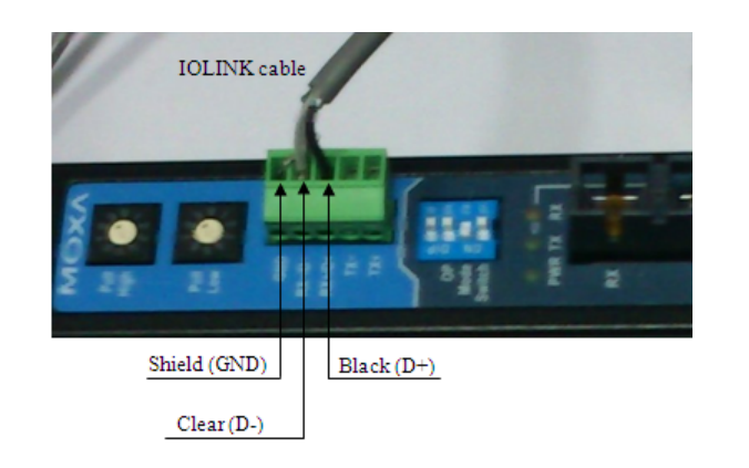
h. Unscrew and remove the I/O Link cable (HPN 51202789-910 / 51202789-911) from the
FOE module or remove the I/O Link connector by pulling it out.
3. Unfasten the screw in the center of the end bracket and remove it by slightly lifting and pulling
it out.
4. Push the FOE module slightly downwards and slide it out at the lower edge of DIN rail


