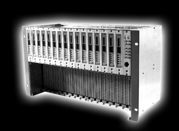
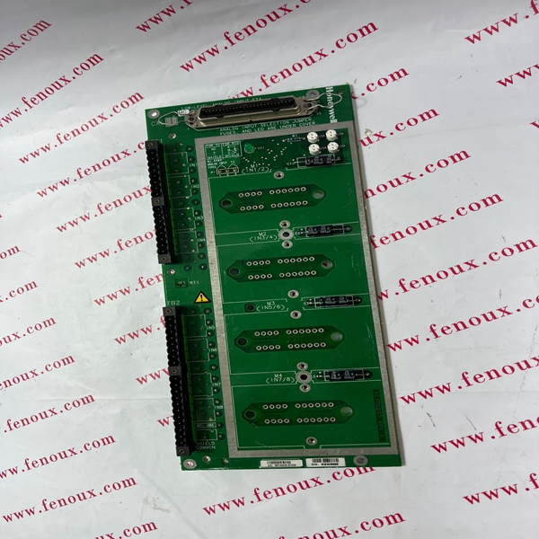
When a module is configured as non-redundant and uses a redundant IOTA, ensure that the lower slot is kept empty or if a module is plugged into the bottom slot, make sure that the module MUST be powered off.
ATTENTION
Be sure to calibrate the position proportional control output so that the increase and decrease
relays operate properly with respect to the position of the external feedback slidewire. Refer to
Section 8 - Output Calibration in this manual.
Table 2-16 Position proportional control output wiring
Step Action
1 Open the recorder door. Loosen the captive screw in the chart plate and swing the plate out.
2 Locate connector J2 and J5 on the control output #1 printed circuit board (refer to Figure 2-17
for location) and remove the unwired plug from J2 and J5.
3 Locate jumper positions W2/W3 and W4/W5 below connector J5 on the printed circuit board.
Remove plug-in output #1 printed circuit board for better access to the jumpers. Be sure to tag
and remove all the plug connections to the printed circuit board before removing it. Position the
jumpers as shown in Figure 2-17 for desired relay contact action. Locate jumper position
W6/W7 on the bottom left portion of the board. Make sure position W6 is selected for position
proportioning, then reinstall the printed circuit board.
4 Run the feedback slidewire and motor drive wires through the desired knockouts.
5 For CE Mark conformity:
· install the ferrite filter as shown in Figure 2-11
· install the shield capacitors as shown in Figure 2-17.
6 Strip insulation from the end of each wire.
7 Loosen the screws in plug J2 terminals and position the plug as you would to plug it into J2.
8 Insert the wires from the motor’s feedback slidewire into the appropriate screw clamps as
shown (refer to Figure 2-17). Tighten the screws to secure the wires.
9 Loosen the screws in plug J5 terminals and position the plug as you would to plug it into J5.
10 Insert the wires for the motor into the appropriate screw clamps as shown (refer to Figure
2-17). Tighten the screws to secure the wires.
11 Install the wired plug into J2 and J5, as applicable.
12 Repeat steps 2 through 11 for Control Output #2 printed circuit board as applicable.
