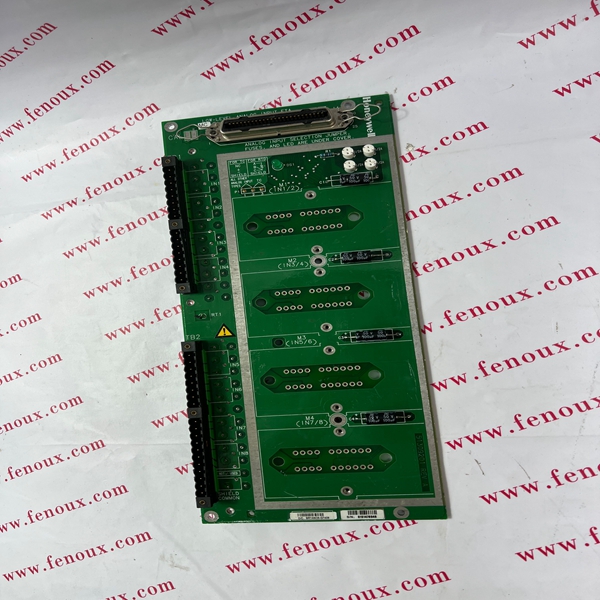
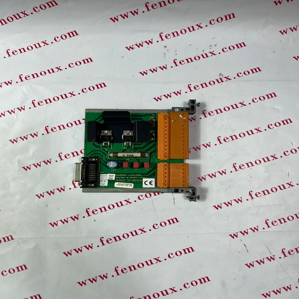
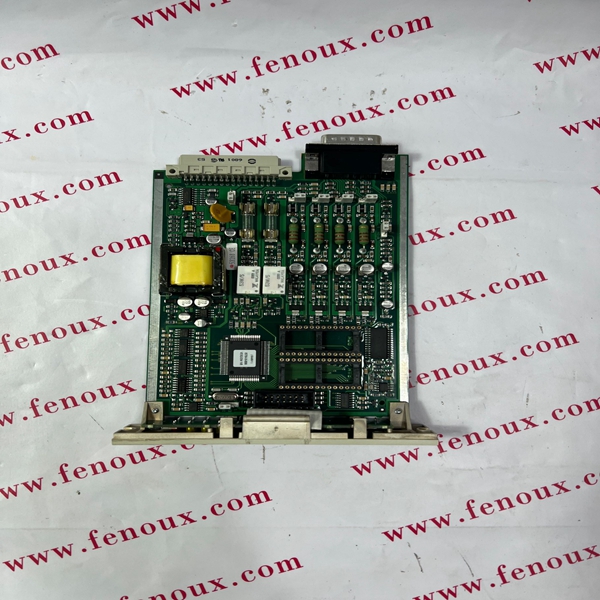
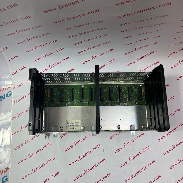
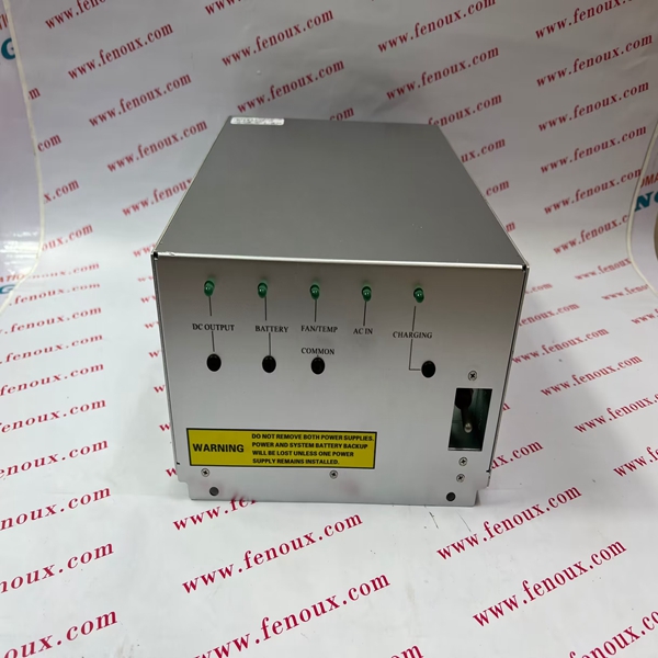
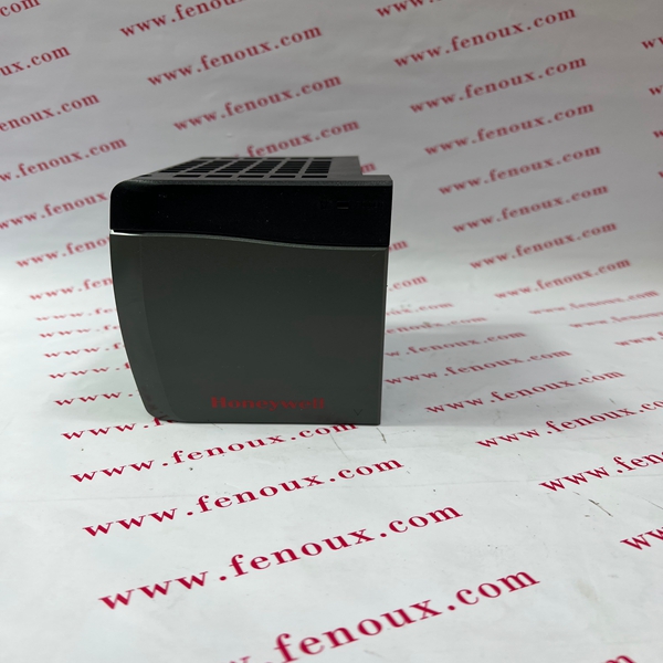
In virtually all configurations, the C300 controller and Series C I/O provides useful, maintainable process equipment connections in a smaller footprint than existing competitors and Honeywell equivalent products. Installing Series C I/O modules contributes to overall total installed cost savings.
The RAM chip can be permanently damaged by incorrect insertion.
(4) Insert the RAM expansion integrated circuit (HN6264ALP) into the
socket IC12 on the Engineering Card, ensuring that pin 1 of the IC
is aligned correctly with pin 1 of the socket and that all pins are
properly inserted into the socket.
(5) Using small pliers or an electrical screwdriver gently remove the
Engineering Card shorting link LK1 and replace to short pins 1 and
2. See Figure 7.
(6) This step applies to the RS485/422 module only. For correct
operation, especially at high baud rates, RS485 and RS422
highways should be resistively terminated.
In RS422 host systems, a terminator resistance is only required at
the receiver device located in the host and at the receiver device
located in the System 57 node at the far end of the cable.
In RS485 host systems, a terminator resistance is required at the
transceiver device located in the host and at the transceiver device
located in the System 57 node at the far end of the cable.
For dual highway RS485 systems, both highways should be
terminated as described above.
By default the RS485/422 module transceivers are unterminated. If
a resistive termination is required, use small pliers or an electrical
screwdriver to gently remove the shorting links, LK2 (Channel 1) or
LK1 (Channel 2), on the RS485/422 Module from pins 1 and 2 and
replace to short pins 2 and 3. (See Figure 1 and Section 3.4.3).
(7) Insert the MODBUS Interface Module into the socket headers J1
and J2 on the Engineering Card, ensuring that pin 1 of the module
pin headers is correctly aligned with pin 1 of the Engineering Card
socket headers.
(8) Re-insert the Engineering Card into the rack, tighten the two front
panel screws and go to the Section 3.4.
