Brand:siemens
Model number:6SL3244-0BB00-1PA1
Colour:new
Warranty: 12 months
Lead Time:3-day working day
Country of origin: USA Price: Please contact us
Product weight:0.3kg
Shipping Port: Xiamen, China
Payment: Bank of Chicago, Bank of Singapore
Express cooperation: fedex, DHL, UPS and your express account
Service: Professional Sales provides 24 hours /7 days online service
Description:
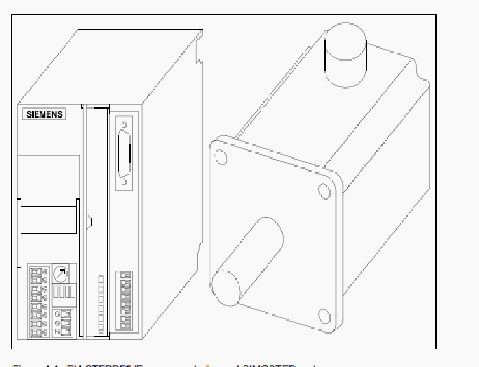
The pulse interface can be used for controlling the power controller from
the master positioning unit using clock signals. With each clock pulse, the
motor moves one step. In addition, a PWM signal can be used for
adjusting the phase current of the stepping motor between 0 and 100 %.
Input signals: PULSE (clock), DIR (sense of rotation), ENABLE
(enables the amplifier), PWM (current control).
Output signal: READY1_N (readiness).
Signal interface The GATE_N input of the signal interface can be used for enabling or
disabling the clock signals for motor control fed to the PULSE input. The
ENABLE_N input has the same function as the ENABLE input for the
pulse interface although it is activated via 24 V. In addition, the ZERO
output can be used for evaluating the zero signal of the internal ring
counter.
Input signals: GATE_N (enabling/disabling the clock signal)
ENABLE_N (enables the amplifier)
Output signals: ZERO (ring counter zero signal), READY2
(readiness),
MSTILL (Motor standstill)
Mains and
intermediate circuit
connection
The mains connection supplies the power controller with 115 V or 230 V
AC. The intermediate circuit connection may be used for dissipating
surplus recovery energy of the motor.
02.05 2 Functional description
© Siemens AG 1998 All Rights Reserved
FM-STEPDRIVE/SIMOSTEP (FB) 2-3
Motor connection A 3-phase stepping motor of the SIMOSTEP series can be connected to
the motor connection.
Current and
parameter switches
These switches are used for setting the motor phase current, the number
of steps (500, 1000, 5000, 10 000 steps/revolution) and the current
reduction
(to 60 % at motor standstill).
LED status
indicators
To indicate readiness and any malfunctions (short-circuit between motor
phases, supply overvoltage/undervoltage, power controller
overtemperature, no GATE_N signal).
Fan A fan is installed in the FM-STEPDRIVE power controller.
The block diagram shown in figure 2-2 illustrates the most important
functional
PULSE (clock) To start motor shaft rotation, rectangular clock pulses must be supplied to
the PULSE input. Each positive pulse edge triggers one motor step if the
power controller is in ready status and the GATE_N input is energized
(24 V).
The sense of rotation is preset with the direction input (DIR).
DIR (sense of rotation) When the DIR signal input is deenergized, the motor turns in a clockwise
direction (as seen from front towards motor shaft). When this signal input
is energized, the motor turns in a counterclockwise direction (as seen
from front towards motor shaft). The sense of rotation can also be
inverted by interchanging two motor phase leads.
ENABLE (enable) When the ENABLE input is energized, the power controller is enabled.
After approx. 500 ms, the power controller reports readiness via the
READY1_N and READY2 outputs and the motor is energized. If 24 V are
present at the GATE_N input of the signal interface, clock pulses can be
supplied to the PULSE input.
PWM (current control) The set motor phase current can be modified using a pulse width
modulation signal on the PWM input in the range from 0% to 100%
(frequency range 10 kHz to 20 kHz). The phase current is determined by
the pulse/pause ratio of the PWM signal. If the signal input is
deenergized, the set phase current flows. If the signal input is energized,
the motor phase current is switched off. When the motor is stopped, it
does not have any holding torque.
Output:
READY1_N (readiness) When the ENABLE input is activated, the power controller reports readiness
via the READY1_N output. When the power controller is ready, the
READY1_N output has low resistance. If 24 V are present at the GATE_N
input of the signal interface, clock pulses can be supplied to the PULSE
input.
In case of a power controller fault, or if a power controller enable signal
has not been received via the ENABLE input, the READY1_N output has
high resistance.
Shipping Port: Xiamen, China
Payment: Bank of Chicago, Bank of Singapore
Express cooperation: fedex, DHL, UPS and your express account
Service: Professional Sales provides 24 hours /7 days online service
Relevant details:
1FT5066-0AK71-1-Z
3TK2827-1AJ20
3TY7561-1A
6ED7193-4CF50-0AA0
6EP1332-1SH12
6ES7132-4BD32-0AA0
6ES7193-4CD30-0AA0
6ES7214-1AC01-0XB0
6ES7810-5CC10-0YR5
6DR2800-8J
6ES7214-1BD23-0XB8
6ES7952-1AP00-0AA0


