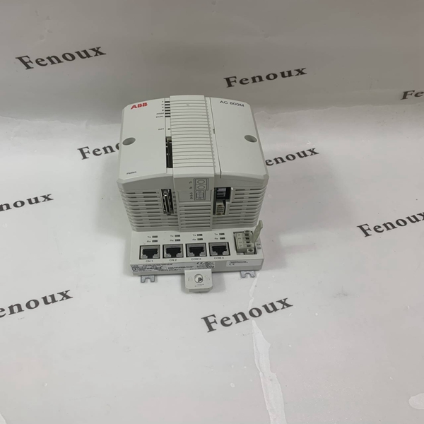
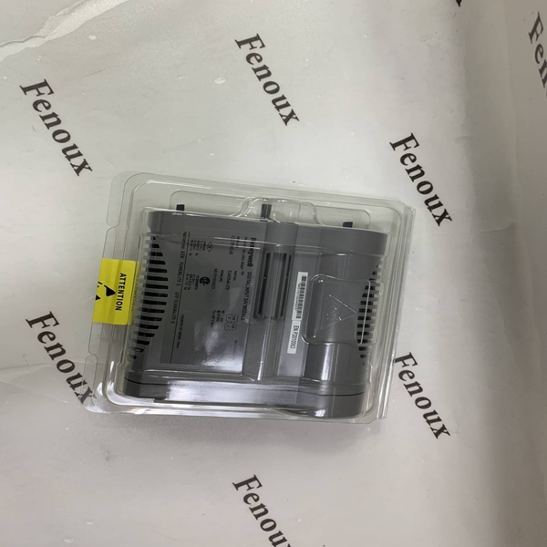
A processor bus adapter (PBA) must be installed on the back of
the module mounting unit when a BRC-100 Harmony Bridge
Controller module is used. The PBA is necessary to connect the
controller module to Hnet for communication with a Harmony
I/O system. The Hnet bus is the communication path between
a BRC-100 module and Harmony I/O blocks.
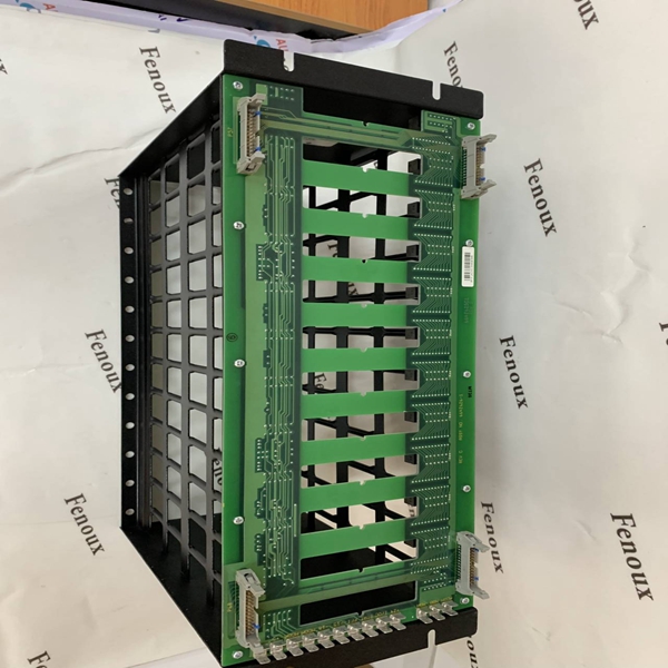
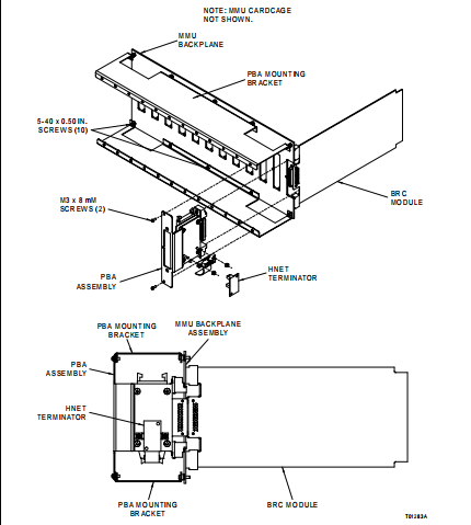
Installation requires attaching PBA mounting brackets to the
back of the module mounting unit, then attaching a PBA
assembly to the brackets in each controller module position.
The following procedure details PBA mounting brackets instal�lation. Refer to the Harmony Bridge Controller instruction
for PBA assembly installation and cable connection.
To install the PBA mounting brackets:
1. Turn off power to the cabinet.
2. Remove the top five screws that secure the backplane
assembly to the back of the MMU.
3. Install one PBA mounting bracket to the top of the module
mounting unit backplane assembly using five of the 5-40
screws provided with the brackets (Fig. 3-3).
4. Remove the bottom five screws that secure the backplane
assembly to the back of the MMU.
5. Install the other mounting bracket to the bottom of the
backplane assembly using five 5-40 screws.
BACKPLANE I/O CONNECTORS
Refer to Table 3-3 for a description of connectors P36 through
P40. Refer to Table 3-4 for a description of connectors P41
through P55. Figure 2-1 shows the locations of all connectors.
Table 3-5 provides a description of the output signal connec�tors, P25 through P35. Figure 3-4 shows the pin location.
WARNING
Disconnect power before installing the processor bus adapter
mounting bracket on the module mounting unit backplane.
Failure to do so will result in contact with cabinet areas that
could cause severe or fatal shock.


