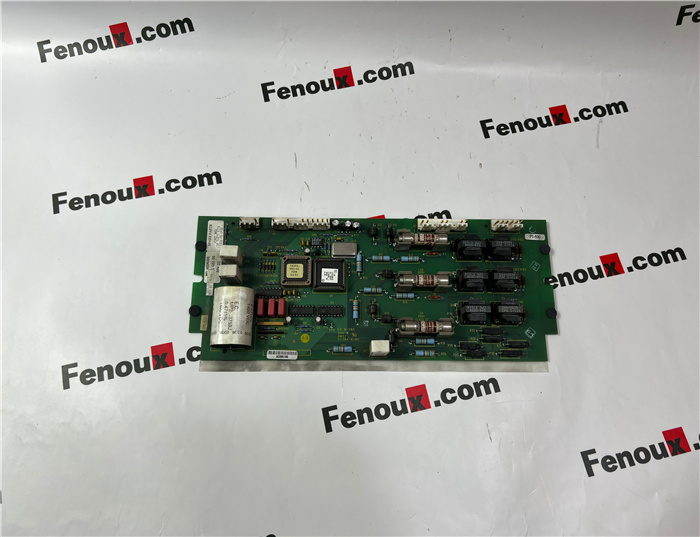
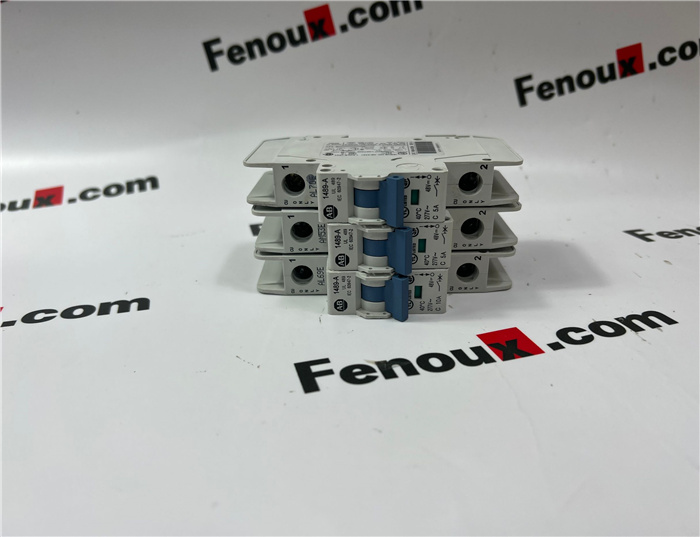
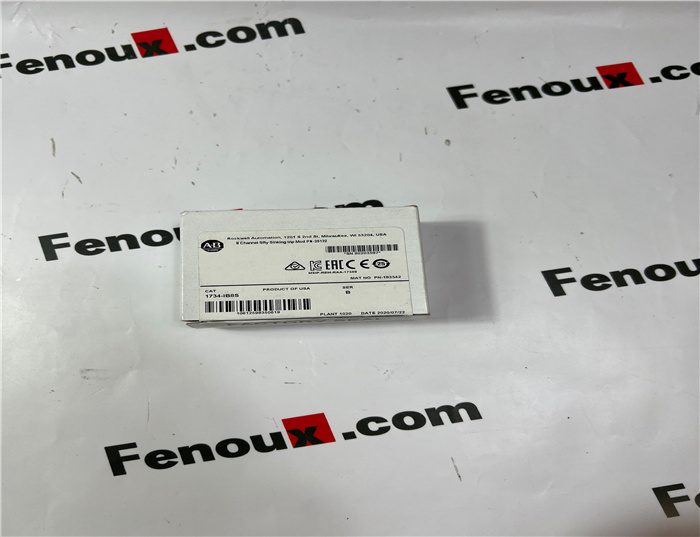
Brand: Allen Bradley
Model number:1485R-P2D5-N5
Colour:new
Warranty: 12 months
Lead Time:3-day working day
Country of origin: USA Price: Please contact us
Product weight:0.31kg
Shipping Port: Xiamen, China
Payment: Bank of Chicago, Bank of Singapore
Express cooperation: fedex, DHL, UPS and your express account
Service: Professional Sales provides 24 hours /7 days online service
Description:
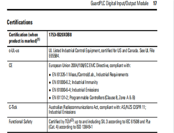
Line Control
Line control is a short-circuit and line-break monitoring system, for example, E-stop inputs that
can be configured for the GuardPLC system. Up to eight digital outputs (DO1…DO8) can be
configured as pulsed outputs. The example below shows two pulse outputs connected to the
digital inputs (DI) of the same system. As a result, the connections to the digital inputs (DI) are
monitored.
Inputs are set to 0, a fault code is generated, and the FAULT status indicator is on when:
• a short-circuit occurs between two parallel connections.
• two connections are reversed.
• earth fault occurs on one of the lines (only with earthed reference pole).
• a line breaks or one of the contacts opens (that is, when one of the E-stop off switches is
pressed in the example above).
Safety-related Digital Outputs
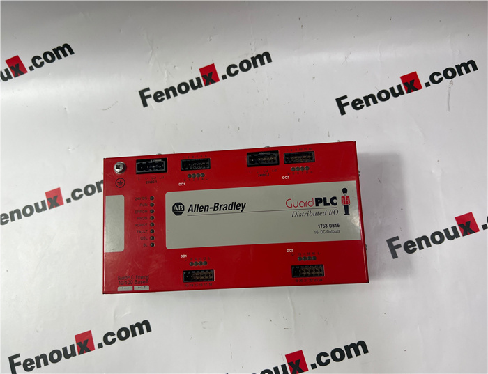
The module has eight digital outputs (DO1…DO8) whose status is indicated via status
indicators.
An output is in a safe state when it is de-energized. If a fault occurs, all outputs are turned off.
Outputs 1…3 and 5…7 can have a load of 0.5 A at an ambient temperature of 60 °C (140 °F).
Outputs 4 and 8 can each have a load of 1 A at an ambient temperature of 60 °C (140 °F), or up
to 2 A at an ambient temperature of 50 °C (122 °F).
With an overload, one or all of the outputs are turned off. When the overload is eliminated, the
outputs are activated again according to the specified value.
Although the external line of an output is not monitored, a short-circuit will be indicated.
The module cannot be panel-mounted. Mount the module to a DIN rail by following the steps
below.
1. Hook the top slot over the DIN rail.
2. Insert a flathead screwdriver into the gap
between the housing and the latch and pull
the latch downward.
3. Hold the latch down as you push the housing
back onto the DIN rail.
4. Release the latch to lock the module onto the
rail.
Ground the Module
The module is functionally grounded through its DIN rail connection. A protective earth
ground connection is required and is provided through a separate grounding screw on the upper
left of the housing and marked with the grounding symbol .
You must also provide an acceptable grounding path for each device in your application. For
more information on proper grounding guidelines, refer to the Industrial Automation Wiring
and Grounding Guidelines, publication 1770-4.1.
IMPORTANT For effective cooling, mount the module following these guidelines.
• Mount the module horizontally.
• Provide a gap of at least 100 mm (3.94 in.) above and below the module.
• Select a location where air flows freely or use an additional fan.
• Do not mount the module over a heating device.
TIP To remove the module from the DIN rail, insert a flathead screwdriver into
the gap between the housing and the latch and pull the latch downward as
you lift the module off of the rail.
Shipping Port: Xiamen, China
Payment: Bank of Chicago, Bank of Singapore
Express cooperation: fedex, DHL, UPS and your express account
Service: Professional Sales provides 24 hours /7 days online service
Related products:
20F11ND027AA0NNNNN
2711-T5A2L1
2711PC-T6M20D
1794-IR8
1756-RM2
1794-OB32P
1794-IE12
22B-D2P3N104
1794-OE12
1794-IRT8XT
1783-AENTR
1394C-SJT10-D


