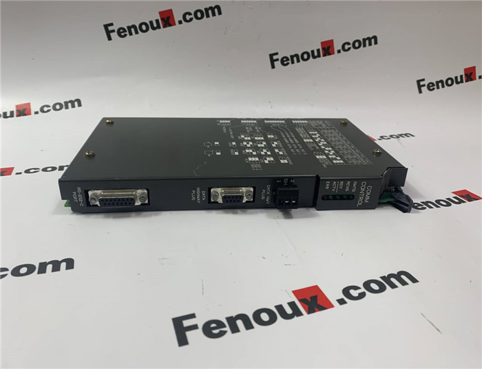
Brand: Allen Bradley
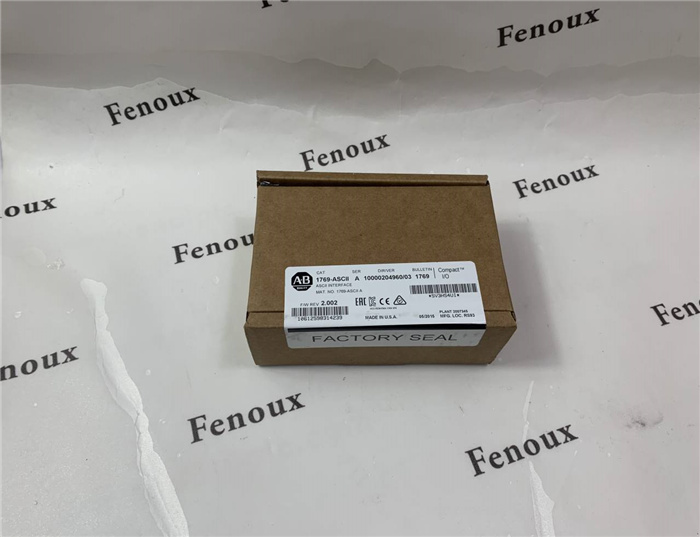
Model number:1769-ASCII
Colour:new
Warranty: 12 months
Lead Time:3-day working day
Country of origin: USA Price: Please contact us
Product weight:0.25kg
Shipping Port: Xiamen, China
Payment: Bank of Chicago, Bank of Singapore
Express cooperation: fedex, DHL, UPS and your express account
Service: Professional Sales provides 24 hours /7 days online service
Description:
1. Disconnect power.
2. Check that the bus lever of the module to be installed is in the unlocked
(fully right) position.
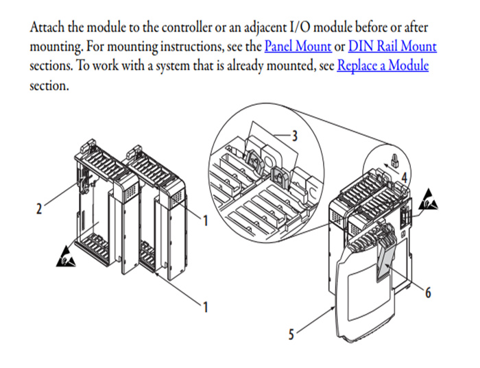
3. Use the upper and lower tongue-and-groove slots (1) to secure the
modules together or to a controller.
4. Move the module back along the tongue-and-groove slots until the bus
connectors (2) align with each other.
5. Use your fingers or a small screwdriver to push the bus lever back slightly
to clear the positioning tab (3).
6. Move the bus lever fully to the left (4) until it clicks, to enable
communication between the controller and module.
7. Verify that it is locked firmly in place.
8. Attach an end-cap terminator (5) to the last module in the system by using
the tongue-and-groove slots as before.
9. Lock the end-cap bus terminator
Panel Mount Procedure with Modules as a Template
The following procedure lets you use the assembled modules as a template for
drilling holes in the panel. Due to module mounting hole tolerance, it is
important to follow these procedures.
1. On a clean work surface, assemble no more than three modules.
2. Mark the center of all module-mounting holes on the panel by using the
assembled modules as a template.
3. Return the assembled modules to the clean work surface, including any
previously mounted modules.
4. Drill and tap the mounting holes for the recommended M4 or #8 screw.
5. Place the modules back on the panel, and check for proper hole alignment.
6. Use the mounting screws to attach the modules to the panel.
If mounting more modules, mount the last one of this group only and put
the others aside. This reduces remounting time during drilling and tapping
of the next group.
7. Repeat steps 1…6 for any remaining modules.
