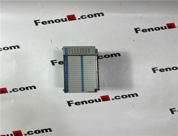
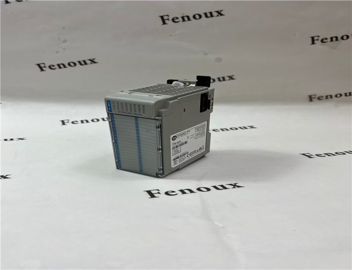
Brand: Allen Bradley
Model number:1769-IQ32
Colour:new
Warranty: 12 months
Lead Time:3-day working day
Country of origin: USA Price: Please contact us
Product weight:0.4kg
Shipping Port: Xiamen, China
Payment: Bank of Chicago, Bank of Singapore
Express cooperation: fedex, DHL, UPS and your express account
Service: Professional Sales provides 24 hours /7 days online service
Description:
System Assembly
The module can be attached to the controller or an adjacent I/O module before or
after mounting. For mounting instructions, see Panel Mounting on page 6, or DIN
Rail Mounting on page 8. To work with a system that is already mounted, see
Replacing a Single Module within a System on page 8.
The following procedure shows you how to assemble the Compact I/O system.
1. Disconnect power.
2. Check that the bus lever of the module to be installed is in the unlocked
(fully right) position
3. Use the upper and lower tongue-and-groove slots (1) to secure the modules
together (or to a controller).
4. Move the module back along the tongue-and-groove slots until the bus
connectors (2) line up with each other.
5. Push the bus lever back slightly to clear the positioning tab (3). Use your
fingers or a small screw driver.
6. To allow communication between the controller and module, move the bus
lever fully to the left (4) until it clicks. Ensure it is locked firmly in place.
DIN Rail Mounting
The module can be mounted using these DIN rails:
35 x 7.5 mm (EN 50 022 - 35 x 7.5) or 35 x 15 mm (EN 50 022 - 35 x 15).
Before mounting the module on a DIN rail, close the DIN rail latches. Press the DIN
rail mounting area of the module against the DIN rail. The latches will momentarily
open and lock into place.
Replacing a Single Module within a System
The module can be replaced while the system is mounted to a panel (or DIN rail).
1. Remove power. See important note on page 4.
2. On the module to be removed, remove the upper and lower mounting
screws from the module (or open the DIN latches using a flat-blade or
phillips style screw driver).
3. Move the bus lever to the right to disconnect (unlock) the bus.
4. On the right-side adjacent module, move its bus lever to the right (unlock)
to disconnect it from the module to be removed.
5. Gently slide the disconnected module forward. If you feel excessive
resistance, check that the module has been disconnected from the bus, and
that both mounting screws have been removed (or DIN latches opened).
NOTE: It may be necessary to rock the module slightly from front to back to
remove it, or, in a panel-mounted system, to loosen the screws of adjacent
modules.
6. Before installing the replacement module, be sure that the bus lever on the
module to be installed, and on the right-side adjacent module are in the
unlocked (fully right) position.
7. Slide the replacement module into the open slot.

Shipping Port: Xiamen, China
Payment: Bank of Chicago, Bank of Singapore
Express cooperation: fedex, DHL, UPS and your express account
Service: Professional Sales provides 24 hours /7 days online service
Related products:
20F11ND027AA0NNNNN
2711-T5A2L1
2711PC-T6M20D
1794-IR8
1756-RM2
1794-OB32P
1794-IE12
22B-D2P3N104
1794-OE12
1794-IRT8XT