introduction:
In industrial applications, 4-20mA analog signals are the most common signal output method. There are several different 4-20mA transmitter wiring options available to meet different needs.
Industrial transmitters are used to monitor various parameters such as pressure, temperature and flow. The transmitter provides a 4-20mA output signal, where 4mA is equivalent to a zero reading and 20mA is equivalent to a full-scale reading. This signal is sent to the remote control panel, which triggers corresponding actions based on the signal, such as audible and visual alarms or initiating some tripping and shutdown procedures. Transmitters typically require 24V DC power, which can be supplied locally or from the control panel.
The following are the different 4-20mA transmitter wiring types:
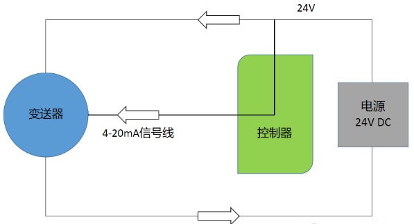
Current source transmitter, non-isolated (3-wire):

The transmitter and control panel can share 24V DC power cords and 0V DC power cords. The 4-20mA signal is transmitted to the control panel via the 24V DC power and signal cables. This wiring method is the most common configuration, requiring only three cable cores and allowing both the transmitter and control panel to use a common power supply. However, since the signal lines may be affected by electrical interference, false alarms may occur.
Current sink transmitter, non-isolated (3-wire):
The transmitter and control panel can share 0V DC power cords and 24V DC power cords. The 4-20mA signal is transmitted to the control panel via the 0V DC power and signal wires. Like the current source transmitter, this wiring method requires only three cable cores and allows the transmitter and control panel to use a universal power supply. However, it is also possible to be affected by electrical interference, causing false alarms.
4-wire full isolation:
The transmitter and control panel are powered by independent power supplies and the 4-20mA signal is transmitted via two independent cable cores. This wiring method can effectively prevent electrical interference from the power line from being transferred to the signal line, reducing the risk of the controller receiving stray signals. But each transmitter requires an extra cable core, and separate power supplies are required for both the transmitter and the control panel.
Two-wire loop powered transmitter:
This wiring method provides power and a 4-20mA signal through a two-wire loop between the transmitter and control panel. However, not all transmitters can be wired this way and will need to be specially designed to accommodate. The advantage of this configuration is low power consumption and the transmitter requires only two cable cores. However, the transmitter consumes some current during a fault condition and the fault signal cannot be set to 0mA, so it is not suitable for control panels that require a 0mA signal for fault indication. At the same time, status signals below 4mA are limited because the available mA range is reduced and not suitable for power-hungry transmitters.
Summarize:
4-20mA transmitters are the most common signal output method in industrial applications. According to different needs and application scenarios, different wiring methods can be selected: current source transmitter, current sink transmitter, 4-wire fully isolated and two-wire loop power supply transmitter. Each wiring method has its own advantages and disadvantages. Current source transmitters and current sink transmitters are both common 3-wire non-isolated wiring methods. They use the same power cord for easy wiring, but are susceptible to electrical interference that may cause false alarms. The 4-wire fully isolated wiring method can effectively prevent interference and maintain signal stability, but requires additional cable cores and an independent power supply. Two-wire loop-powered transmitters have low power consumption but are unable to set the fault signal to 0mA during fault conditions and are limited to a smaller current range.
Overall, choosing the appropriate wiring method depends on the specific application needs and environmental conditions. Understanding the characteristics and limitations of different wiring methods can help us make informed choices.


