As soon as a phase threshold is running, the instantaneous output associated with this threshold is activated. This output indicates that the protection element has detected a phase fault and that the time delay associated with the threshold has started.
MiCOM P125/P126 & P127 Page 31/96
The general stability conditions can be obtained when:
Vs> K.If (RCT + 2RL)
Where K is the stability factor.
This stability factor is influenced by the ratio Vk/Vs which in turns governs the stability of the
REF protection element for through faults .
Vk = The Knee point voltage of the CT.
To obtain a high speed operation for internal faults, the Knee point voltage Vk of the CT must
be significantly higher than the stability voltage Vs . A ratio of 4 or 5 would be appropriate.
For MiCOM P121, P122 and P123, we found the following results:
K= 1 for Vk/Vs less or equal to 16 and
K= 1.2 for Vk/Vs > 16.
NOTE: The maximum internal fault level for stage 3 of 0.002 to 1In board
must not exceed 20In.
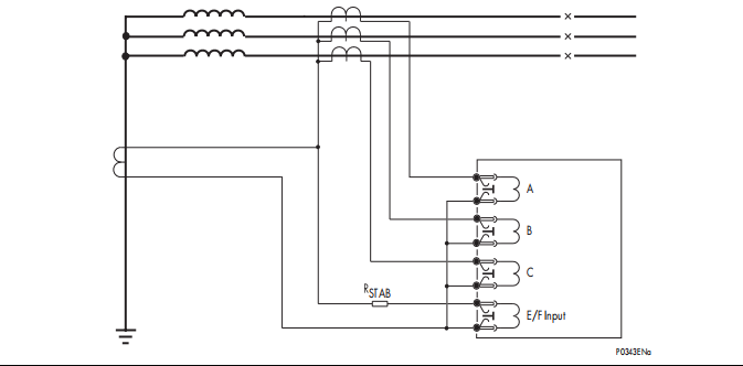
STAB
A
B
C
E/F Input
P0343ENa
CT CONNECTION DIAGRAM FOR HIGH IMPEDANCE REF APPLICATION
2.10.3 Setting guide
The characteristics of the relay and the value of K influence the stability of the scheme as
explained here above.
The typical setting values shall be chosen to provide a primary operating current less than
30 % of the minimum earth fault level for a resistance earthed system. For a solidly earthed
system, the typical setting shall provide an operating current between 10 and 60 % of the
rated current.
The primary operating current, at the secondary, depends on the following factors:
− Current Transformer ratio
− Relay operating current IS
− Number of CT in parallel with the relay element (n)
− The inrush current of each CT (Ie) at the stability voltage
Iop= CTRatio .(Is + n.Ie)
Current setting should be selected for a high impedance element so that the primary current
reaches its nominal current with a given CT, according to the following equation:
Is < {(Iop / CTRatio) - n.Ie}


