The protection element also provides a non-sensitive area to avoid instability due to small asymmetries and unbalances that can generally be present in the network system. This condition is represented by the characteristic reproduced below, where the hatched area is the tripping zone.
Introduction
The restricted earth fault relay is a high impedance differential scheme which balances zero
sequence current flowing in the transformer neutral against zero sequence current flowing in
the transformer phase windings. Any unbalance for in-zone fault will result in an increasing
voltage on the CT secondary and thus will activate the REF protection.
This scheme is very sensitive and can then protect against low levels of fault current in
resistance grounded systems where the earthing impedance and the fault voltage limit the
fault current.
In addition, this scheme can be used in a solidly grounded system. It provides a more
sensitive protection, even though the overall differential scheme provides a protection for
faults over most of the windings.
The high impedance differential technique ensures that the impedance of the circuit is of
sufficiently high impedance such that the differential voltage that may occur under external
fault conditions is lower than the voltage required to drive setting current through the relay.
This ensures stability against external fault conditions and then the relay will operate only for
faults occurring inside the protected zone.
2.10.2 High impedance principle
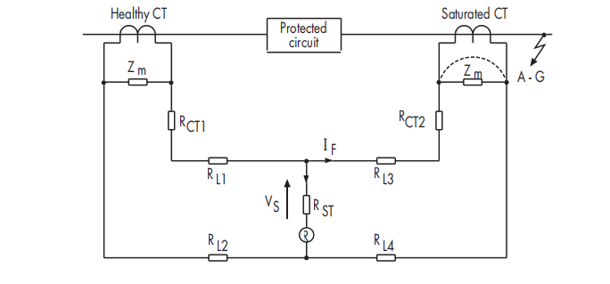
High impedance schemes are used in a differential configuration where one current
transformer is completely saturated and the other CTs are healthy.
Healthy CT
Z m
RCT1
R L1
VS R ST
R L2 R L4
R L3
R
RCT2
Z m A - G
Saturated CT
Protected
circuit
I F
HIGH IMPEDANCE SCHEME PRINCIPLE
The voltage applied across the relay is:
Vr=If (RCT + 2RL)
If : Maximum secondary external fault current.
RCT : Resistance of the Current transformer secondary winding.
RL : Resistance of a single wire from the relay to the CT.
A stabilizing resistor R ST can be used in series with the relay circuit in order to improve the
stability of the relay under external fault conditions. This resistor will limit the spill current
under Is.
Vs=Is (RST)
Is: Current relay setting
Vs: Stability Voltage setting
Note that the relay consumption has been taken into account.


