The TAC Stainless Plate temperature sensors aremounted on the back of a 1 Gang stainless steelplate. The foam pad will insulate the sensor from any drafts in the wall. (2) 6/32” x 1” machine screws are provided for junction box mounting. Be sure that the sensor is not mounted on an outside wall, due to the extreme temperature changes from either drafts or heat transfer.
MiCOM P125/P126 & P127 Page 31/96
The general stability conditions can be obtained when:
Vs> K.If (RCT + 2RL)
Where K is the stability factor.
This stability factor is influenced by the ratio Vk/Vs which in turns governs the stability of the
REF protection element for through faults .
Vk = The Knee point voltage of the CT.
To obtain a high speed operation for internal faults, the Knee point voltage Vk of the CT must
be significantly higher than the stability voltage Vs . A ratio of 4 or 5 would be appropriate.
For MiCOM P121, P122 and P123, we found the following results:
K= 1 for Vk/Vs less or equal to 16 and
K= 1.2 for Vk/Vs > 16.
NOTE: The maximum internal fault level for stage 3 of 0.002 to 1In board
must not exceed 20In.
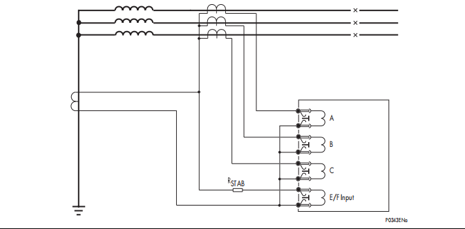
STAB
A
B
C
E/F Input
P0343ENa
CT CONNECTION DIAGRAM FOR HIGH IMPEDANCE REF APPLICATION
2.10.3 Setting guide
The characteristics of the relay and the value of K influence the stability of the scheme as
explained here above.
The typical setting values shall be chosen to provide a primary operating current less than
30 % of the minimum earth fault level for a resistance earthed system. For a solidly earthed
system, the typical setting shall provide an operating current between 10 and 60 % of the
rated current.
The primary operating current, at the secondary, depends on the following factors:
− Current Transformer ratio
− Relay operating current IS
− Number of CT in parallel with the relay element (n)
− The inrush current of each CT (Ie) at the stability voltage
Iop= CTRatio .(Is + n.Ie)
Current setting should be selected for a high impedance element so that the primary current
reaches its nominal current with a given CT, according to the following equation:
Is < {(Iop / CTRatio) - n.Ie}


