If the panel meters show that the generator voltage is different from that of the bus, the voltage offset potentiometer may need adjustment. Make sure that the
panel meters are accurate, calibrated, and at operating temperature. Most panel meters are accurate to ±3% and are not temperature compensated.
Setting Guidelines
The applied current settings for directional overcurrent relays depend on the specific
application. In a parallel feeder arrangement, load current is always flowing in the non�operating direction. Consequently the relay current setting may be less than the full load
rating of the circuit, typically 50% of In.
Note that the minimum setting that may be applied has to take into account the thermal
rating of the relay. Some electro-mechanical directional overcurrent relays have continuous
withstand ratings of only twice the applied current setting. Therefore 50% of rating was the
minimum setting that had to be applied.
With the latest generation relays the continuous current rating is 4 x rated current. If required
it is now possible to apply much more sensitive settings.
In a ring main arrangement, it is possible for load current to flow in either direction through
the point where the relay is located. Consequently the current setting must be above the
maximum load current, as in a standard non-directional application.
The required relay characteristic angle (RCA) settings for directional relays will depend on
the exact application in which they are used.
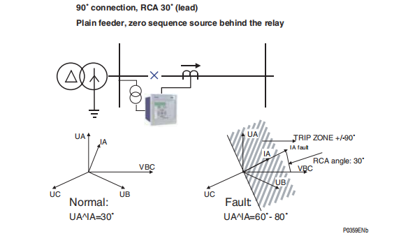
For instance for plain feeders where the zero sequence source is behind the relay, a RCA of
30° should be set.
The following picture shows the above examples.
RCA angle: 30˚
UA
UC UB
IA
VBC
Normal Fault :
UA^IA=30˚
UA
UC
IA
VBC
P0359ENb
:
UA^IA=60˚- 80˚
90˚ connection, RCA 30˚ (lead)
Plain feeder, zero sequence source behind the relay
TRIP ZONE +/-90˚
IA fault
UB
On the P127 relay, it is possible to set the relay characteristic angle (RCA) or torque angle,
as it is also called, in the range of 0° to +359° in steps of 1°. The trip boundary zone
associated to the RCA is settable in the range from ±10° to ±170° in steps of 1°.
Further information about the setting range for the directional overcurrent protection are
available in the Technical Data document


