The TAC Stainless Plate temperature sensors aremounted on the back of a 1 Gang stainless steelplate. The foam pad will insulate the sensor from any drafts in the wall. (2) 6/32” x 1” machine screws are provided for junction box mounting. Be sure that the sensor is not mounted on an outside wall, due to the extreme temperature changes from either drafts or heat transfer.
The A phase charging current (Ia), is then shown to be leading the resultant A phase voltage
by 90°. Likewise, the IB phase charging current leads the resultant voltage Vb by 90°.
The unbalance current detected by a core balance current transformer on the healthy
feeders can be seen as the vector addition of Ia1 and Ib1 (Ia2 and Ib2), giving a residual
current which lies at exactly 90° anticipating the polarising voltage (Vr=3Ve).
The vector diagram indicates that the residual currents on the healthy and faulted feeders,
IH1& IH2 and IR3 respectively, are in opposite direction to each other (180°). A directional
element could therefore be used to provide discriminative earth fault protection.
If the polarising voltage of this element, equal to 3Ve, is shifted through +270°, the residual
current seen by the relay on the faulted feeder will lie within the operate region (Trip Zone) of
the directional characteristic. As previously stated, the required RCA setting for the sensitive
earth fault protection when applied to insulated systems, is 270°.
2.4.3 Wattmetric (Pe) Characteristic
The P125, P126 and P127 relays include the zero sequence power measurement function.
They also offer the possibility to choose between a Wattmetric (Pe) protection and IeCos
(active component of the earth fault current) protection functionality mode.
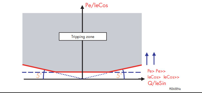
The following figure shows the characteristic tripping zone for the wattmetric protection.
Pe> Pe>>
IeCos> IeCos>>
Pe/IeCos
Q/IeSin
5˚ 5˚
Tripping zone
P0365ENa
In the following formula the power thresholds in the relay menu are called Pe> & Pe>>.
The Pe> and Pe>> settings are calculated as:
Vres x Ires x Cos (f – fc) = 9 x Ve x Ie x Cos (f – fc)
Where:
f = angle between the polarising voltage (Vres) and the residual current
fc = relay characteristic angle (RCA/torque angle)
Vres = residual voltage
Ires = residual current
Ve = zero sequence voltage
Ie = zero sequence current
2.4.3.1 Setting Guidelines for Pe Thresholds
The Pe thresholds are displayed in the format: ##.## x Ien W
In this formula the ##.## setting value is multiplied by the setting value of the Ien.
The threshold value is expressed in Watt secondary.
Example: The Pe> threshold is to be set from the relay front panel and the setting value is
20W.


