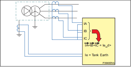
When setting the relay characteristic/torque angle for the three phase directional overcurrent element, a positive angle setting was specified. This was due to the fact that we consider as polarising voltage, the phase voltage value in quadrature of the current under fault conditions. With directional earth fault protection, the residual current under fault conditions lies at an angle lagging the polarising residual earth fault voltage.
Application Considerations
The protection Pe> and Pe>> require relay current and voltage connections to be actived.
The measurement of the Pe depends on the voltage wiring of the relay.
In case of 3Vpn wiring the Ve will be equal to Ve= 1/3(Va+VB+VC) in the other insertions
way the applied voltage to the relay is directly used to calculate the Pe.
Referring to the relevant application diagram for the P125, P126 and P127 relays, it should
be installed such that its direction for forward operation is 'looking into' the protected feeder
i.e. away from the busbar, with the appropriate RCA .
Resistance earthed systems 180°
Insulated systems 270°
Petersen Coil system 200°
Transmission Systems (solidly earthed) 90°-120°
As illustrated in the relay application diagram, it is usual for the earth fault element to be
driven from a core balance current transformer. This eliminates the possibility of spill current
that may arise from slight mismatches between residually connected line CTs. It also
enables a much lower CT ratio to be applied, thereby allowing the required protection
sensitivity to be more easily achieved.
2.4.5 Iecos protection
The Iecos protection follows the same concepts of the Pe protection.
The difference is that the thresholds take in account the active component of the earth fault
current.
The setting of the RCA follows the above listed table.
2.4.6 Where use Iecos and where use Pe.
The wattmetric protection Pe/Iecos is almost used in the Petersen Coil systems.
In a Petersen Coil scheme during a fault we have a resistive current and an inductive
current.
The resistive current is constant because the residual voltage is always present; the
inductive current is the summation of the capacitive contribution of the healthy line and the
reactive contribution of the fault line.
In this situation is difficult to discriminate the line and detect the fault current value because
the capacitive and reactive are of opposite sign.
Since the residual voltage is present to the parallel between the coil and resistance a
wattmetric protection is used to be sure to open the fault line.
The unique resistive present component depends on the fault line.
The discriminative for the using of Pe or Iecos protection is the fault current value and the
relative fault operating boundary.
In some applications, the residual current on the healthy feeder can lie just inside the
operating boundary following a fault condition. The residual current for the faulted feeder lies
close to the operating boundary


