Prior to commissioning ensure that all measuring devices are connected in correct phase sequence. The connect command for the unit circuit breaker must bedisconnected at the unit circuit breaker. The field rotation must be monitored for proper rotation. Any absence of or incorrect connection of voltage measuring devices or other signals may lead to malfunctions and damage the unit, the engine, and/or components connected to the unit
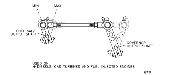
Manually stroke the fuel control linkage from stop to stop as if the actuator were
moving it. The linkage must move freely without friction and without backlash.
Lubricate or replace linkage or fuel control parts as required.
Mount the actuator and install a suitable linkage.
EPG Electrically Powered Governor Manual 82493
8 Woodward
A return spring is included in the actuator. Do not use an additional return spring.
(Low force return springs that may be located in an engine’s valve cover usually
don’t affect EPG performance.)
Make sure that the actuator is capable of moving the fuel control to the maximum
and minimum limits. Let the fuel control limit actuator travel. Set the linkage so
that the actuator is just above minimum when the fuel control is at its minimum
stop and (except for Detroit Diesel engines) so that the actuator is just below
maximum when the fuel control is at its maximum stop. We recommend that
Woodward installation kits be used for Detroit Diesel engines.
Use good rod end connectors. The link connecting the actuator lever to the fuel
control lever must not be so long that it flexes when the prime mover is running.
Installing the Magnetic Pickup
Mount the magnetic pickup through a housing or rigid bracket. Make sure that the
sensed gear is of magnetic material. The gap between the pickup and the
outside diameter of the gear should be set to approximately 1.0 mm (0.04”) at the
closest point (radial runout). Using the pickup with small gears may require
spacing as close as 0.25 mm (0.010”).
If you cannot measure the gap directly, it can be set in this manner: with the
prime mover shut down, turn the pickup in (clockwise) until it touches the outside
diameter of a tooth. Then back out the pickup (counterclockwise) approximately
three-quarters of a turn. Run the gear slowly through 360 degree rotation to
check the clearance of the pickup. When the gap is set, tighten the jam nut
securely against the housing or bracket.
The standard pickup models require mating connectors, MS 3102R-18-3P. The
connectors are not furnished with the pickup, but may be ordered from
Woodward if desired. See manual 82510, Magnetic Pickups and Proximity
Switches for Electronic Controls, for more information
