Speed Control
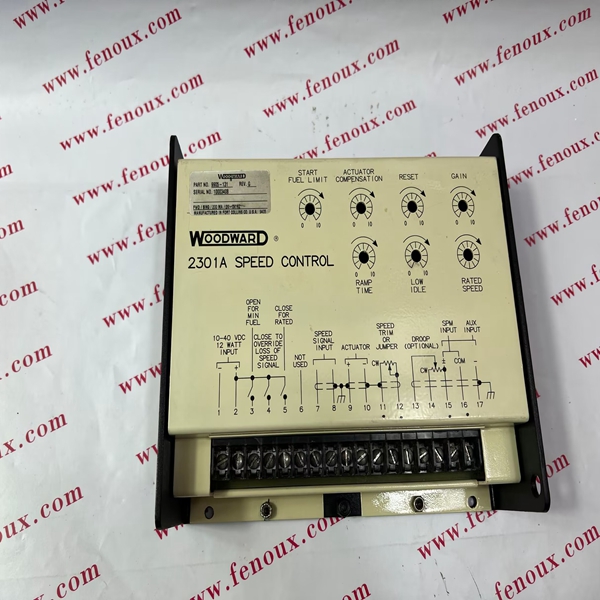
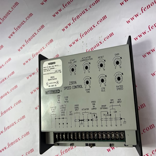
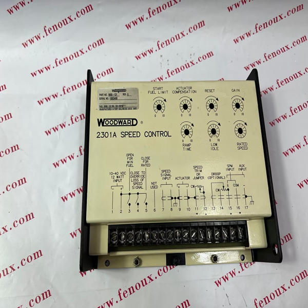
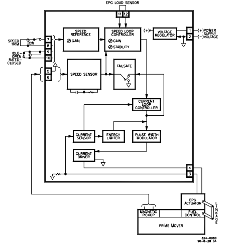
The basic speed control components and connections are shown in Figure 1-1.
There are no mechanical drive or hydraulic connections. All input power comes
from the battery. The speed control compares the actual speed with the desired
speed. It then calculates an error signal and drives the actuator in the increase or
decrease fuel direction to correct prime mover speed.
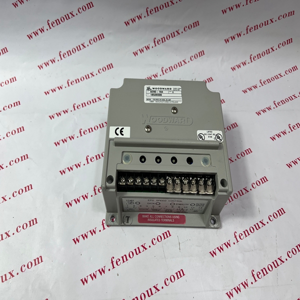
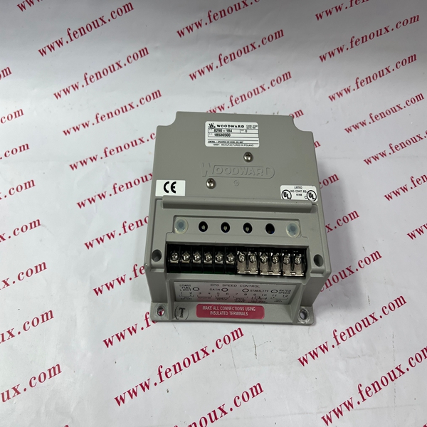
Figure 4-1 shows the Electrically Powered Governor in more detail. The speed
control is housed in a die-cast aluminum enclosure.
The EPG has two control loops. The speed loop ensures prime mover speed
remains constant. The current loop ensures proper drive to the actuator.
Speed Loop
The speed loop controller has two inputs: the desired speed (speed reference
signal) and the actual speed (the speed sensor signal). It compares the two and
calculates an error signal which includes dynamic response considerations. Gain
and stability adjustments tailor the governor’s response to the requirements of
the specific prime mover. Rated speed is set by the rated speed pot and, if
attached, a speed trim pot. The idle reference is controlled by an external idle
speed pot. Rated speed should be set before idle speed. Speed sensor output is
a voltage proportional to magnetic pickup frequency. The frequency range of the
magnetic pickup is set by an internal resistor. The specific frequency range of a
specific EPG Speed Control is indicated by the part number of the speed control.
Current Loop
The current loop error signal can be considered a command for the correct
amount of actuator current.
The actuator’s controller circuit compares actual current (from the current sensor
circuit) to the desired current level (from the speed loop controller) and generates
a current loop error signal. To make the current driver efficient, it is operated as a
switch. Actuator current is changed by changing the duty cycle. The pulse width
modulator converts the current loop error signal from a dc voltage to a switching
signal. For this reason measurements of speed control output [3 (+) and 4 (–)]
indicate only general conditions. Excessive currents are prevented from flowing
through the actuator coil by the energy limiter. It prevents the actuator from
overheating but allows enough current to keep the actuator at the maximum fuel
position.
The auxiliary input is jumpered except when a Load Sensor is added for
paralleled generator applications. There is a failsafe circuit which senses MPU
frequency and forces the pulse width modulator input to zero if the MPU
frequency or voltage are below acceptable limits, as they would be if an MPU
wire broke.


