To prevent damage to electronic components caused by improper handling, read and observe the precautions in Woodward manual 82715, Guide for Handling and Protection of Electronic Controls, Printed Circuit Boards, and Modules.
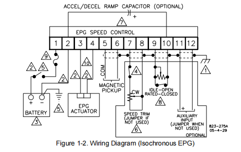
Shielded wires to be twisted pairs or twisted 3-conductor, grounded at one end only.
2. 4 or 2 mm² (12 or 14 AWG) stranded wire, must be as short as possible and routed
as a pair ≤10 mm apart. Total of distance from battery to control, and from control to
actuator, to be as short as possible (see maximum length in chart).
Note: In expensive AC to DC Battery chargers used for maintaining the battery
charge allow moderate surges from the AC mains to couple to DC power:
To protect the EPG a surge arrestor of at least the energy & voltage
capability of a V47ZA7 MOV should be placed from battery minus to battery
plus terminals.
3. See EPG Models above for source voltages.
4. Open for minimum fuel. Do not use either the minimum fuel option, or disconnect the
actuator leads, or disconnect the power to the control as part of any emergency stop
sequence.
5. For positive ground systems, switch and fuse to be located in series with battery (–)
and terminal 2. Positive (+) terminal becomes chassis ground. Leads from battery to
terminals 1 and 2 must be direct and not pass through distribution points.
6. Approximate speed change with trim potentiometer:
±2.5% using a 1 kΩ potentiometer
±5% using a 2 kΩ potentiometer
7. About one second ramp time per 50 µF. Capacitor specification: 200 µF maximum,
15 W minimum, less than 30 µAdc leakage current over temperature range.
8. Idle range about 25% to 200% of rated, using 50 k potentiometer. For fixed idle,
calculate the value of the resistor:
R = 17 kΩ ( Rated Speed
Idle Speed – 1 )
9. 512/24 and 1712/24 use a 10 A fuse.
10. Polarity not important.
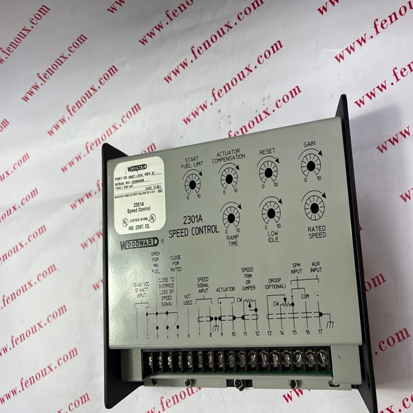
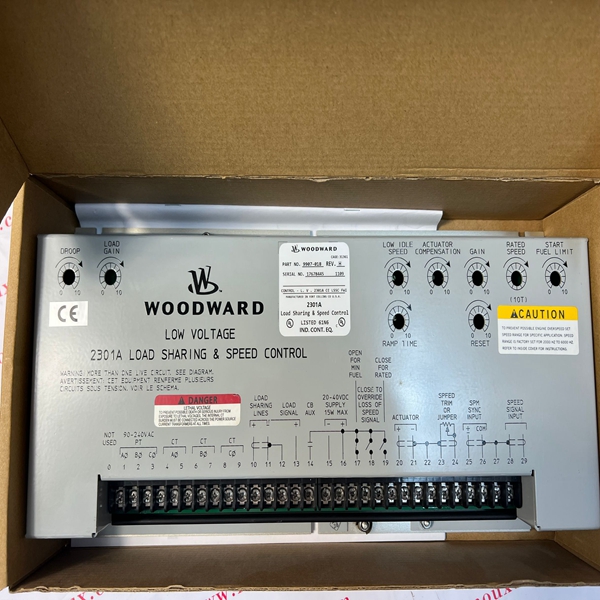
11. With a balanced load and unity power factor (PF=1), the current transformer should
be wired in the correct potential leg, and must be phased at the control so the
potential at terminal 9 to 10 is in phase with the CT from terminal 11 to 12.
12. Power source current transformers should be sized to produce a 5 A secondary
current, with maximum generator current. CT burden is essentially 0 VA.
13. Absolute minimum signal must be 95 Vrms. Absolute maximum signal must be 260
Vrms. Potential transformer burden is 20 VA.
14. This control contains an internal current transformer. This transformer must be
connected across the power source transformer whenever the unit is running to
prevent lethal high voltage from developing on leads to these terminals.
15. On systems without a neutral, the voltage at terminal 9 to 10 is 1.73 times N2/N1
times the line-to-line voltage
