Do NOT use the minimum-fuel contact as a part of any emergency stop sequence. The emergency may be caused by a governor malfunction which would also cause a malfunction of the minimum�fuel feature. Use of the minimum-fuel contact for an emergency stop sequence could cause overspeed of the prime mover and mechanical
damage and personal injury, including death.
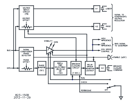
The following instructions and wiring diagrams illustrate typical wiring
connections. For applications not shown in Figures 2-1 and 2-2, refer to the plant
wiring diagram (Figure 1-4) or contact Woodward for assistance.
Connect the synchronizer terminals as shown in Figure 1-4. When making the
connections, observe the following:
· Make all connections using insulated terminals.
· Use 0.5 mm² (20 AWG) or larger stranded, twisted shielded wire.
· Make sure that all wires shown as shielded on the plant wiring diagram, are
shielded.
· Do not place shielded wires in the same cable conduits with high-voltage or
high-current carrying cables.
· Do not connect the cable shields to any external grounds. The shields are
grounded at the control end only.
· Make sure that cable shields are carried through all intermediate terminal
blocks from signal source to signal termination.
· Do not subject any wiring to temperatures above 100 °C (212 °F).
· Avoid kinks or sharp bends in the wiring.
· Make sure that all connections are tight.
For additional wiring information, see Woodward Manual 25070, Electric
Governor Installation Guide.
Install and wire the other units and actuators in your system using instructions in
applicable manuals.
Connections to the Generator
The synchronizer is powered by voltage supply connections to the generator
potential transformers (PTs). It uses a standard 120 Vac or 208/230 Vac, 50/60
Hz input. The synchronizer can use the same voltage connections to the
generator PTs as the electronic governor's load sensor. Power consumption of
the synchronizer is 5 W maximum.
1. Connect the generator PT neutral to synchronizer terminal 5 (Figure 2-1).
2. Connect one phase of the generator PT (usually phase A) to synchronizer
terminal 2.
3. Connect the same phase from the bus PT to synchronizer terminal 6.
4. Connect bus neutral to terminal 9.
